Description
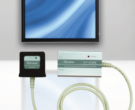
The Chroma A712306 Flicker Measuring Probe for LCM ATS is specifically designed for adjusting the flicker on LCM automatically following the FMA(Flicker Modulation Amplitude) standards defined by VESA (Video Electronics Standards Association) and JEITA( Japan Electronics Information Technology Industries Association) for flicker measurement. It can work with the Chroma 291X Series LCM automatic test system to complete auto flicker adjustment.
The main function of Chroma 291X Series LCM ATS is to provide the power and signal for the LCM to be adjusted. Different model no. and accessories can be purchased based on the interface and size used. The A712306 that is controlled by 291x LCM ATS follows the VESA defined FMA measurement to retrieve the flicker value for judgment. When the flicker value is larger than the specification, the flicker adjustment interface will be used to adjust the Vcom voltage on the UUT (Unit Under Test.) The flicker adjustment with patented algorithm can adjust quickly and complete the entire program in seconds.
The auto flicker adjustment program equipped by Chroma 291X Series LCM ATS can edit different scripts for different models of UUTs without burning in the firmware. Such flexibility is suitable for most of the LCMs with digital Vcom functions on the market that can improve the test efficiency, lower down the test equipment and labor cost for the LCM manufacturers.
FMA Measurement Theory
Assuming the luminance change of LCD is as the figure shown below, the luminance of AC is Vmax-Vmin and the luminance of DC is (Vmax+Vmin)/2.
Based on the calculation formula of VESA, FMA: FMA = AC lux. / DC lux. = (Vmax-Vmin)/{ (Vmax+Vmin)/2} x 100%
FLVL Measurement Theory
The way of FLVL is sending the data A712306 measured to the filter whose sensor is fit to human eyes. Then output it into the FFT Analyzer. Get the energy distribution in different frequencies.
Here’s the JEITA standard flicker calculation formula: Flicker amount = 10 x log (Px/P0) [dB]
* P0: Power spectrum when frequency is zero
* Px: Power spectrum when frequency is X Flicker